Introduction | Bed Selection module | Graphics Module | Data Message Processing Module | The Bed Data Class | Bed Data Member Functions | Main Program | Testing
Following initialisation of the Careplane interface board and establishment of a logical source for data messages, the application layer can begin data acquisition. At any time, there are a variable number of active bedside monitors, each with a variable number of medical parameters. The application runs on a remote computer, so the user is not able to determine which bedside monitors are active simply by glancing around the ward. To assist in the selection of a bed for remote monitoring, the application layer presents a list of active beds, and prompts the user to select one. In addition, for each bed a list of the available parameters is presented. If the logical bed number is not known, the parameter list may help to identify the correct bedside monitor. The implementation of the bed list is discussed in depth in the next section.
The main data acquisition loop uses a C++ class to create a Bed Data object with member functions to:
The application layer is also responsible for setting the display adapter to graphics mode and drawing the separate data acquisition windows. Finally, the module for detecting and reading the data messages sent by Careplane in response to a session layer request forms a crucial part of the application layer. As Careplane has limited buffering capability, the timing of data reading assumes greater importance. A data message must be read, formatted, displayed and possibly written to file within a maximum of one system cycle (1024 ms) if uninterrupted data flow is to be maintained.
Creating the linked list of bed nodes | Displaying the available parameters | Prompt the user to select a bed | Checking that the bed is in the list | Deleting the list
At the start of the main program loop, the user is presented with a list of active bedside monitors on the network. The bed selection module uses the polling transmission mode to identify the active monitors. A connect request is sent by the session layer with the following syntax:
ConLSReq ISDReq = DefConLSReq;
  ISDReq.LSN = 0x00;
  ISDReq.LB8to1 = 0xFF;         // All Beds
  ISDReq.LB16to9 = 0xFF;
  ISDReq.LB24to17 = 0xFF;
  ISDReq.DataClass1 = 0x01;     // IS Data
  ISDReq.Mode = 0x00;           // Poll
The request specifies:
An Instrument Status (ISD) data message is returned by each active bedside monitor on the network, one per monitor per system cycle. It contains information about the parameter and wave types available from each bed. Parameter data is either single- or triple-valued numeric data, updated every system cycle. Waveform data for the electrocardiogram (ECG), arterial (ABP), pulmonary artery (PAP) and central venous pressures (CVP) are also available, with a sampling frequency of 125Hz (500Hz for ECG). If the connect request is accepted, Careplane responds with an acknowledgement, but a poll request is required to retrieve the IS data. The sequence is therefore:
ConnectLS(&ISDReq);
sleep (2);
PollLS(0);
BedSelected = GetActiveBeds();
It is important to give Careplane at least one system cycle (1024 ms) to gather the IS data, otherwise one or more active beds may be "missed". In practice, 2 seconds are allowed. As a consequence, a bed may appear more than once if 2 consecutive system cycles include IS data from this bed. In other words, a bed may "come around again" in the next system cycle. The bed selection module can detect these duplicate beds, and exclude them from the list. The detailed format of Careplane data messages is given in Appendix A, but a brief outline is given here for clarity. Each message has a 4 byte preamble, and a variable number of variable-length elements, consisting of a 6 byte header followed by the data. The format of a typical IS data message is given in Figure 4.1. The poll request sent by the session layer will attempt to read 4 bytes from shared memory to confirm that the request was successful. Unlike other session layer requests, Careplane will not acknowledge a successful poll request. Instead, it simply sends the data message(s) specified in the request. Polling therefore reads the first 4 bytes of the message. If it is a data message, the first 4 bytes are the preamble. The next byte in memory is the first byte of the header of the first element.
Figure 4.1 Typical Data Message containing Instrument Status Data
        The length field of element 2 = 0, indicating that it is the last element
The first field of each element header is the length of the element, and is crucial to the process of reading through the data. If the length is zero, then it is the last (or only) element, and only 1 word is received. Otherwise, the message is read an element at a time until the final element is reached. For a source defined to include Instrument Status data from all beds, the number of elements corresponds to the number of active beds, one element per bed. The data message in each element contains codes for the active waves and parameters available from the bed. This is the information required for the bed list, but only the active parameters will be displayed at run time. To improve the efficiency of memory usage, a linked list data structure is used to store the codes for the active waves and parameters from each bed, as their number is not known at compile-time. This is implemented as:
struct BedNode {
  byte BedNum;
  BedNode *NextBed;
};
BedNode *FirstBed, *LastBed, *ThisBed;
FirstBed = LastBed = ThisBed = NULL;
To process the data message, a pointer is declared: byte *DataPtr for stepping through each single byte field. For clarity, 3 structures are declared to hold the values in the element header and the Instrument Status message, struct ElementHeader, struct ISDMsg and struct ISData The active parameters may then be referred to as members of the ISData structure (see Appendix C for complete code listing).
An array of type byte is declared to hold each element, with a maximum length of 200 bytes. The average element length is 30 to 40 bytes, so this is quite generous. In pseudocode, the bed list module proceeds as follows:
Read the length of the first element
While the length is greater than 6 bytes {
  Read the rest of the header and assign to an ElementHeader structure
  Read the rest of the element (the data message) and assign to an ISDMsg
  Check that this is an instrument status message
  Check the flags to detect a monitor that is in self-test
  Move the data pointer to the beginning of the wave/parameter data codes
  If the bed list is incomplete {
    create a new Bed Node
    if this is the first bed { display the available parameters }
    if this is the first bed coming around again {
        delete it
        set the bed list to complete
    }
    else { display the available parameters }
  }
  Get the length of the next element
} while the length is greater than 6
6 bytes is the minimum element length that may be read safely, as the message length (in words) is calculated as (ElementLength/2) -3. A negative value passed to CplRead() will produce a fatal error. In practice, the shortest element other than a terminating element is 6 bytes plus the IS data message, which is a minimum of 16 bytes, even if there are no parameter and wave data codes.
The operators new and delete are used to allocate memory for a linked list of bed nodes. In addition to the *Next pointer, each node has a single data member containing the bed number (figure 4.2)
Figure 4.2 Linked List of Bed Nodes
After creation of a new BedNode, an assertion is made to ensure that memory has been allocated, although it would be preferable to use an exception handler here.
When all logical beds on the SDN are active, they total 15 in number. To display all 15 on a single screen, the text mode is switched to 80 columns by 50 lines. 4 lines are required for the header and user prompt, leaving a maximum of 3 lines per bed for information. The format is therefore:
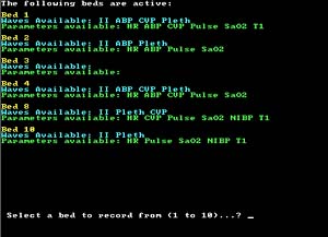
Function void DisplayBedStatus(byte *WPPtr, byte NumW, byte NumP, byte BedNum) takes a pointer to the first available wave or parameter, the number of waves available, the number of parameters available and the logical bed number. Each wave or parameter is assigned to an ISData structure, and the member ISData->WPFC is used to access the actual code for the wave or parameter. Unfortunately, when decoded, some of the parameters and waves in the message are classed as unavailable (code 0). These are skipped over and the valid parameter codes are displayed.
Function int GetBedFromUser(void) displays a prompt at the bottom of the screen and takes a 2-character string using:
cin.get(cinstr,3,'\n');
This is converted to a long int:
BedSelected = strtol(cinstr,NULL,0); and the input stream is flushed:
do {
   c = cin.get();
  } while (c != '\n');
The value of BedSelected is returned.
To ensure that a valid bed has been selected, the value of BedSelected is compared with the BedNum member of each BedNode. The bed list is stepped through until the bed is found, in which case BedFound becomes True and control passes to the next code block. If the bed is not found, control passes back to the call to GetBedFromUser().
When the user has selected a valid bed, the bed list is no longer required. It is deleted from start to end using the delete operator. Finally, the bed selection module returns the value of the bed selected.
A separate module configures the host computer's display adapter for VGA resolution graphics (640 x 480 pixels, 16 colours). If the adapter does not support VGA mode, an error message is displayed, and the program terminates. The main parameter acquisition screen has 4 areas (figure 4.3) :
Figure 4.3 Main Parameter Acquisition Window
When a new logical source has been connected using the logical bed number supplied by the user, data messages begin to arrive in the receive buffer. If the receive buffer becomes full, new messages will overwrite old, and messages will be lost. To read every message, each one must be copied from the receive buffer and processed before the buffer becomes full. It is up to the programmer to decide how frequently to copy messages, and in this application, every data message is read and copied. Not all messages encountered in the receive buffer will be data messages. If the user requests that the source be disconnected, a disconnect response will appear. Applications that have defined more than 1 logical source must also distinguish between messages from different sources. In this application, a single source is defined for parameter data from a single logical bed, and all data messages originate from this bed.
Function int ReadMsg(BedData*); takes a BedData object from the main program (discussed in depth below) and returns 1 when acquisition has been terminated successfully. ReadMsg() is responsible for copying messages from the receive buffer in a repeating loop, until the user presses a key. Unlike the Bed List module, data transmission is automatic (rather than poll), and each data message arrives with a preamble, followed by the header and the message itself. Two message types are requested:
A feature that is not fully explained in the Careplane supporting documentation is the use of certain parameters as remote event markers. In the course of programming this module, it was discovered that temperature data was inconsistent with that displayed on the monitor in the ward. It seems that under certain conditions, the bedside monitor will mark an event, and a code for this event is transmitted as temperature data. To get the real temperature, a second message class is requested - Parameter Support Data (PSD). This message contains an ASCII text field with the actual text displayed on the bedside monitor. Function GetTemp (byte*), discussed below, is responsible for processing the PSD message and extracting the temperature data.
The control logic of ReadMsg() can be summarised as:
Repeat {
    Wait for a message
    Decode the message - is it Data or a Disconnect Response?
    if Data {
      Is it Parameter Value or Parameter Support Data?
        if Parameter Value {
            Read the entire message
            Update parameter data members of the BedData object
            (Display on monitor/Write to file)
        }
        if Parameter Support Data {
            Read the entire message
            Extract the temperature data
        }
    }
    if Disconnect Response {
        check to ensure that disconnect was successful
        return to main program
    }
} Until user presses a key
Return to main program
One PSD message is broadcast every system cycle (1024 ms) for each active parameter in the source. For example, a source with 5 active parameters will broadcast 5 PSD messages per system cycle, but only 1 PVD message. Each PSD message contains a 20-byte text field with the ASCII equivalent of the displayed numeric values. Only one of these PSD messages contains the ASCII temperature data. To prevent unnecessary searching of the messages, a boolean variable LookForTemp is set to True when a temperature message is found (a typedef statement declares boolean as an alias for type int, True and False are symbolic constants with value 1 and 0 respectively). GetTemp() searches the text string for 'T1', 'T2' or 'Tb', indicating the first or second non-specific temperatures, or the blood temperature. If any of these are found, strtol() is used to convert the numeric characters in the string to a long int, which is returned by GetTemp().
To facilitate the processing and display of parameter values and parameter support data from a data message, an object of class BedData is created in the main program and passed to ReadMsg(). The class has 11 data members and 16 member functions, some of which are described briefly below. The use of a class to encapsulate the data and functions improves program clarity and readability (figure 4.4). A limited amount of range checking is also performed on the setting of the logical bed number.
Figure 4.4 Bed Data Class class illustrating the linked list of ParamNode structures and the four main member functions.
At the heart of the BedData class are 3 ParamNode structures that form a linked list, similar to the BedNode list described in the Bed Selection module.
struct ParamNode {
  byte MFC, // medical function code
       Val, // 0:valid, 2:questionable,3:useless
       MCC, // magnitude conversion code
       Type;    // single- or triple-valued
  int  Value1,
       Value2,
       Value3;
  boolean Display;
  char DisplayValue[10];
  char DisplayTime[15];
  ParamNode *Next;
};
The list is used to hold the current parameter values. It is created every 4th data message, the parameters are displayed and then the list is deleted. An identical list is created every 58th message for writing the parameters to a file, and then this list is deleted. Along with the numeric values in the PVD message are byte fields containing:
A complete listing of the medical codes is given in Appendix C, file mfc.cpp, and the magnitude conversion code table is given on page 34. Single numeric values are sent for parameters such as heart rate, oxygen saturation and central venous pressure. Triple numeric values are sent for (most commonly) arterial and pulmonary artery pressures and non-invasive blood pressure, where the order is systolic, diastolic, mean. Cardiac output (CO) and pulmonary capillary wedge pressure (PCWP) are also triple numeric values, but the second and third values are the time of measurement, encoded as hour (0-23):minute (0-59).
Figure 4.5 ParamNode data structure containing the actual parameter values.
1.Constructor | 2.Create and update parameter list | 3.Format parameters for display | 4.Display parameters | 5.File I/O | 6.Utilities
void BedData::SetBedNum(int LBN) The constructor takes a single integer argument to set data member BedNum. It is checked to ensure that it is in the range 1 - 24. If the value is outside this range, BedNum is set to 1. The constructor has a default argument setting BedNum to 1.
void BedData::UpdateData(byte *DataPtr, int TVal) Each node in the linked-list of parameter nodes contains the information for a single parameter value. Each time that fresh data becomes available from the SDN, a list of nodes is created and initialised with the new data. In the hours following the admission of a patient to the ITU, new parameters such as pulmonary artery pressure, cardiac output and associated variables may become available. This presents no difficulty for the creation of the parameter list, as its size can grow and shrink, but the module that handles file I/O needs to know about such changes in order to update the parameter column headings. BedData has a data member boolean NPchanged that is a flag for changes in the number of parameters reported by a bed. It will also detect a decrease in the number as happens, for instance, when recording modules are removed from the bedside monitor (see chapter 1, Bedside Monitors for a description of plug-in modules).
Several parameters must be excluded from the displayed list. A bed that is recording SaO2 will also have the pulse rate available, measured from the pulse plethysmograph. It is uncommon for the pulse/heart rate to be unavailable from the ECG, so the Pulse parameter is not displayed. As indicated on page 29, temperature data is obtained from a PSD message, so the temperature data in the PV message (which may be invalid) is not displayed. Each parameter node contains a boolean variable Display that is set to False for Pulse and the 3 temperature parameters (T1, T2 and Tb).
UpdateData() is passed a pointer to the address of the parameter in memory, and uses it to step through the parameter values, assigning the data to the appropriate field of the ParamNode structure. Several pitfalls await the unwary programmer. The parameter values are encoded in two byte fields, with the most significant 2 bits in the first byte, and the least significant 8 bits in the second field (figure 4.6)
Figure 4.6 Parameter values are encoded as 10-bit integers in 2-bit and 8-bit fields. Bit positions 0-9 are shown for 3 values, but in the case of a single-valued parameter, only value 1 is received.
To unite the value in a single 16-bit field, the most significant 2 bits are left-shifted 8 positions, and the least significant 8 bits are added to this value:
ThisP->Value1 = (*DataPtr)*256;
  DataPtr++;
  ThisP->Value1 += (*DataPtr);
A further difficulty to overcome is the encoding of signed integers. A 3-bit magnitude conversion code (MCC) accompanies each parameter value, which is decoded as follows:
|
Value |
MCC |
|
Unsigned 0 to 1023 |
000 |
|
Unsigned 0 to 102.3 |
010 |
|
Unsigned 0 to 10.23 |
100 |
|
Signed -512 to +511 |
001 |
|
Signed -51.2 to +51.1 |
011 |
|
Signed -5.12 to +5.11 |
101 |
Signed values are detected as follows:
if ((ThisP->Value1 > 511) && ((ThisP->MCC) & 0x01 == 1))
Finally, signed integers are in twos complement form, with bit 10 as the sign bit. The value is corrected by subtracting 1024:
|
Decimal |
Binary |
511 = |
01 1111 1111 |
-512 = |
10 0000 0000 (twos comp) |
=
|
10 0000 0000 (converts to 512) |
512 - 1024 = -512
void BedData::FormatForDisplay(void)
The actual value displayed is stored in DisplayValue, a 10-character string field in the ParamNode structure. Three attributes of the parameter require attention before the value is displayed on the screen:
Validity checking is done using the validity flag:
0 = valid
2 = questionable
3 = invalid
For valid parameters, no further processing is necessary, and execution falls through to the code for scaling. Questionable values are marked by filling DisplayValue with "??" for single- or "???/??(??)" for triple-valued parameters. Stored parameters are ignored at this point, as they are handled separately later in the function. Similarly, DisplayValue is filled with "--" or "---/--(--)" for invalid parameters.
In the latter 2 cases, scaling is unnecessary, so boolean variable Scale is set to False. The code for scaling is enclosed in a conditional if (Scale) { } compound statement block.
If the MCC indicates that the value is to be treated as non-integral, scaling is required. To avoid the use of floating-point arithmetic, the values are displayed with the decimal point inserted at the appropriate place. For instance, to format the value 381 with MCC = 011:
sprintf(ThisP->DisplayValue,"%d.%d",ThisP->Value1/10,ThisP->Value1%10);
will display the value 381 as 38.1
Stored parameters such as CO and PCWP have the time of recording encoded in the second and third values. These are handled separately, with validity checking and scaling applied as appropriate. As an example, assume that the CO is encoded in three values: 366,1,28, with the MCC indicating an unsigned value between 0 and 10.23. Formatting will allow the value to be displayed as CO 3.66 at 01:28.
void BedData::DisplayData(void)
DisplayData() steps through the parameter list, displaying each parameter in a vertical list in the left pane of the display window (see Figure 4.3). The temperature (if available) is appended to the bottom of the list. A utility member function SetTextColor(byte) sets the appropriate text colour for the parameter. The colours chosen correspond as closely as possible to the colours on the bedside monitor, within the limits imposed by 16-colour VGA graphics. The display update interval is every 4 messages, or every 5 seconds, approximately. In the interval between display updates, data messages continue to arrive and are read, but the parameter list is not updated. After display, the parameter list is no longer required, and is deleted.
void BedData::WriteHeader(char* PName, char* Stud, char* Diag)


     void BedData::WriteParamList(void)


     void BedData::WriteNewParamList(int NumPVP)


     void BedData::WriteParamsToFile(void)
4 member functions are used to save consecutive parameter data to a disk file. A comma-separated value (*.csv) format was chosen to produce a file that is readable by any text editor, and is also recognised by Microsoft Excel. When the file is opened by this spreadsheet application, data may be charted, subjected to statistical analysis or copied easily into other applications.
WriteHeader() is called from the main program prior to data acquisition and is discussed in that section.
The control logic for writing to file may be summarised as:
Update the parameter data for the bed
Check the start flag
If the start flag = 0 {
  Write the parameter column headings
  Set the start flag to 1
}
else if the number of parameters has changed
  Write a new parameter list
else
  Write the parameters to the file
WriteParamList() creates column headings for the parameter data. It is called immediately before the first data write to file. To prevent WriteParamList() from being called at every file write, BedData has a private data member StartFlag that is initialised to 0 at the beginning of the program. StartFlag is checked prior to calling WriteParamList(), 0 indicating that this will be the first call. Following the first call to WriteParamList(), StartFlag is set (i.e. assigned the value 1), preventing subsequent calls.
When UpdateData() detects a change in the number of parameters, another private data member of BedData, NPChanged is set to True This will provoke a call to WriteNewParamList() which inserts a message in the file to notify the reader that the number of parameters has changed, and creates a new row of parameter column headings. Assuming that the number of parameters hasn't changed at the next file write, NPChanged is reset to False.
If none of the above conditions are true, the parameter data is written to the file as a comma-separated list of values, followed by a new line. Each data entry in the file is time-stamped with hour:minute. As an example, the following would appear in the file as a single entry for 4 parameters:
Time,HR,ABP,,,CVP,SaO2
23:12,60,120,70,95,8,98
and if viewed as an Excel spreadsheet:
|
Time |
HR |
ABP |
CVP |
SaO2 |
||
|
23:12 |
60 |
120 |
70 |
95 |
8 |
98 |
A file update interval of approximately 64 seconds, or every 60 data messages was chosen, but this can be altered easily at compile-time. After the parameters have been written to file, the parameter list is no longer required, and is deleted to recover memory.
The remaining six member functions of the BedData class performs various utility tasks such as checking, setting and clearing StartFlag, setting the text colour for displayed parameters, checking for changes in the number of reported parameters from the bed and returning the current number of parameters.
Control logic for the main program may be summarised as:
Initialise Careplane
Loop
  Connect a logical source for Instrument Status data
  Wait for Careplane to acquire the most recent data
  Poll this logical source
  Display the bed selection screen and prompt the user to select a bed
  Disconnect the logical source
  Connect a new logical source for PVD and PSD
  Prompt the user for data for the file header
  Read and process messages until the user quits
  Disconnect the logical source
  Ask the user if he or she wants to view the bed list again
  If Yes,
    Repeat
  Else Quit
The creation of the Connect, Poll and Disconnect requests is covered in chapter 3 (Session Layer).
The main program creates a new BedData object for each data acquisition run, deleting it when the user either quits the program or begins a new acquisition run. After a bed has been selected, the byte field of the connect request that specifies the logical bed number(s) for recording must be modified. For example, suppose the user selects Bed 7. The LB8to1 field in the connect request must be set to:
|
0 |
1 |
0 |
0 |
0 |
0 |
0 |
0 |
or 0x64 (2^6) in hex. A utility function int ConvertBedToHex(int BedSel) takes the bed number (1 to 24) and returns the required value, which is then assigned to either LB8to1, LB16to9 or LB24to17 for the appropriate logical bed number. The user can quit from the program by entering 0 at the bed selection prompt. In this case, the bed selected is returned as 25 and a boolean variable AcqData is set to False. Data acquisition will only proceed if AcqData is True. At this point, the user may elect to view the bed list again, by which time the bed of interest may have become active or else quit the program. If a valid bed is selected, a prompt is displayed for the text information that will appear as the header in the data file. This data is written to the file, and the main data acquisition loop begins.
A number of non-fatal error conditions may arise during this loop, some of which are coded in the return value of the data message processing module. In each case, Careplane is returned to a stable state, a text error message is displayed on the screen and the program terminates.
When a data acquisition run is completed, a prompt is displayed asking whether the user would like to view the bed list again. If not, the program terminates.
Over the course of the project, several hundred hours of data recording have been logged. Several conditions have resulted in non-fatal run-time errors, others in fatal run-time errors.
A recurring error is caused by a break in the data stream longer than 12 seconds i.e. longer than the timeout value built into the DLCL read process. Speculative causes of these breaks in the data stream include:
An unexplained fatal error has occurred several times. Upon checking the status LEDs on the Careplane board itself, the idle LED is lit steadily, indicating either that there is no data being transmitted by the SDN, or that there is a hardware fault not covered by the status LEDs. There is no hardware support from HP for the board, and no further progress with this error was made.